Chapter Contents:
3.1 Tools for Representation of Programs
3.2 Flowcharts and Structured Flowcharts
3.3 Pseudocode
3.4 Warnier-Orr Diagrams
3.5 Questions
3.6 Exercises
3.2 Flowcharts and Structured Flowcharts
3.3 Pseudocode
3.4 Warnier-Orr Diagrams
3.5 Questions
3.6 Exercises
3.1 Tools for Representation of Programs
The goal of representation is to show the structure of the programming steps in as clear and straight-forward a manner as possible. Many details are deliberately left out in the representation step. In this step one needs to see the "big picture".
Representation is typically used throughout the whole development cycle of a program. In the beginning it is helpful for putting down one's ideas on paper in a form that can be readily understood by others. It is used throughout the design process (see next chapter). Once the program is written, representation tools help document the program so it can be easily understood my maintenance programmers.
The particular tool or tools you use for representation may be a matter of personal taste, or may be dictated by your instructor or the organization you work for. In any case, there are advantages and disadvantages in every technique. They are usually not very hard to learn and can be extremely valuable.
In this class the representation tools give us a way to talk about programming steps in class without having to write code. That way we can compare various methods of solving problems without getting lost in the syntax of a particular language.
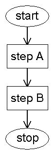
Flowcharts show the flow of control through a program in a graphical form. For example,
if step A is processed before step B (sequence) that part of the flowchart would look
like this:
Selection is represented with a diamond. Inside the diamond is the condition that
is evaluated in the selection. There are always two lines leaving the diamond that
are labeled "Y" or "N" (for "yes" and "no", but some authors use "T" and "F" for
true and false). Here's a simple flowchart for selection:
In the above flowchart step A is executed only if the variable A is greater than
zero. If A is less than or equal to zero step B is executed. There are many variations
on this theme. For example instead of doing one step if A>0, there may be many steps
instead of just one. Or there can be no steps, or there could be a selection or a repetition.
Likewise for the other path (A<=0). Or there could be nothing, or a sequence, selection or
repetition structure instead of step B.
We saw in the last chapter that repetition comes in several forms. In a pre-test loop a
loop condition is tested at the
top of the loop. In a post-test loop the loop condition is tested at the bottom of the
loop. Here is a flowchart that shows the flow of control in a pre-test loop:
In this case step A is repeated as long as the variable A is greater than zero. Note that
if A is less than or equal to zero when it enters the structure then step A will not be
executed even one time.
The following is an example of a post-test loop.
In this case step A is executed and then the value of the variable A is tested. If A>0
then step A is executed again. Otherwise control exits the loop. Note that in this case
step A will always execute at least once.
There is not a special flowchart for finite repetition. In actuality finite repetition is
made using a pre-test loop with a built-in counter. Most modern languages have provide a
special structure for finite iteration so you don't need to do the counter incrementation
yourself.
Structured Flowcharts
The simple flowcharts shown above for sequence, selection and repetition can be
combined to form very complex flowcharts. However, the programs they represent might not
be "structured" programs. Some flowcharts can only be programmed by using GOTO statements.
If a flowchart represents a program that can be written entirely with programming structures
without using any GOTO statements,
then it is a "structured flowchart". There are special rules that flowcharts must follow
to be structured. Simply put, the basic flowcharts shown above can be combined to make
structured flowcharts, but only if the structures are properly nested. Any structure can
be used inside another structure, but only if it lies completely inside the outside
structure. In other words the inside structure must replace one of the blocks labeled
"stepA" or "stepB". There must not be any lines from inside the structure block (stepA or
stepB) to any point outside the block.
Pseudocode should not be confused with real program code. Its purpose is to allow one to
easily communicate one's ideas with others without the extra complexity of a real language.
Pseudocode is usually used without following any formal rules. When you write it you
include whatever complexity is necessary to describe the situation at hand.
Sequence
In pseudocode sequence is represented by adjacent program steps. For example, a process
that can be broken down into three steps might look like this:
Selection
Selection is usually represented with the keyword "if". In this case there is the
need to show what is contained within the selection structure. Some programmers like
to use other keywords like "BEGIN" and "END" (following COBOL). Others like to use
braces "{" and "}" (following C language). In either case the relevant block for the
selection is clearly marked as in the following examples. There are numerous variations
and all of the following should be understood to mean selection regardless of exact syntax
of the pseudocode:
From now on we will use a form of pseudocode that most closely resembles the C language (the
right-most example).
Exclusive Selection
Recall from the last chapter that exclusive selection is where executing a block within
a selection structure excludes execution of all other blocks within that structure.
Exclusive selection is indicated with the keyword "else". Here's a pseudocode example of
a simple exclusive selection structure with two possible outcomes:
Repetition
Repetition is represented by several different pseudocode structures. There are many variations.
Finite representation is often represented as follows (very close to Basic language):
Combinations of Structures
As an example of more complex pseudocode imagine a program that reads a file of customer names and
purchases. The goal of the program is to calculate and print the total amount of all purchases,
but only include purchases that have been delivered. In this example a C-language
style while loop and if block are used:
Warnier-Orr diagrams use pseudocode to show program steps. Flow of the program starts at
the top of the diagram and moves toward the bottom. The left-hand side of the diagram shows
the program in its least detailed form. As you move to the right in the diagram you see
more and more detail.
Sequence
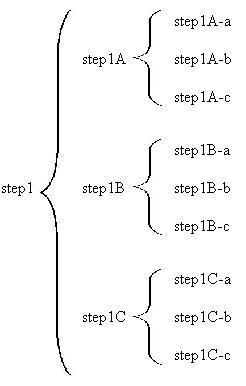
In our first example we'll consider only sequence. Consider a program step that consists of
several substeps, each of which has several steps. At the lowest detail level the step can
be represented as a single statement of pseudocode:
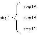
If each substep has substeps they are represented by braces for each substep to the right
of the substeps as in the following diagram.
You keep adding more detailed steps to the right until an appropriate amount of detail
is provided. Note that some steps may require more detail than others.
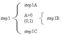
Selection
Selection is represented by a condition expression with the string (0,1) under the
condition to represent that the step is performed zero or one time depending
on the outcome of the condition test. Immediately to the right of the condition is
a brace containing the step or steps to be executed if the condition evaluates to true.
In the following, step1 consists of several substeps, but step1B will only be executed
if the variable A is greater than zero.
Exclusive Selection
There are times when selection must be exclusive. This means (looking at the previous example)
that if step1B is
executed it should not execute step1C even if its corresponding condition is true.
Exclusive selection is represented by two or more condition expressions with
A common exclusive programming structure is the "if-else if-else" structure. This structure always has
an "if" part, may have zero to N "else if" parts and may have one optional "else" part.
The Warnier-Orr diagram uses the
Repetition
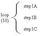
Repetition is represented with a brace and the number of times the loop will execute underneath
the pseudocode name of the step. If there is one number it is called "finite repetition".
The loop executes a fixed number of times (known ahead of time).
Here's an example of finite repetition. The substeps will execute 10 times:
Warnier-Orr diagrams can easily include complex combinations of various programming
structures. With practice you will be able to write Warnier-Orr diagrams of arbitrary
complexity.
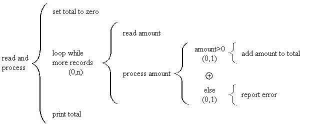
As an example consider a program step that reads all the records of a file
and calculates and prints a total, but only includes positive amounts. Negative or zero amounts
are reported as an error. It might look something like this:
We will see many examples of Warnier-Orr diagrams in the next chapter.
3.2 Flowcharts and Structured Flowcharts
Flowcharts are useful for quickly visualizing the flow of control in a program.
Flowcharts are covered at length in PH110. If you haven't taken that class yet, you
will very shortly (since it is a prerequisite for just about every CM class after
CM111). In this work we will show some of the simpler aspects of flowcharts to help
support the material in the lectures.
Flowchart for Sequence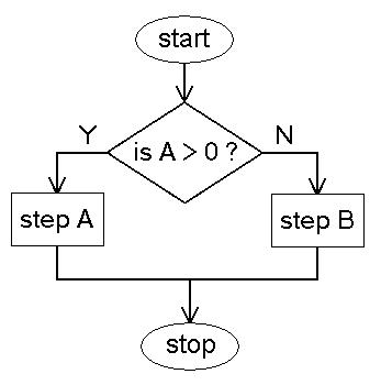
Flowchart for Selection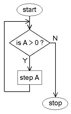
Flowchart for Pre-test Repetition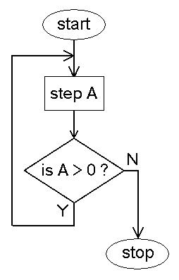
Flowchart for Post-test Repetition3.3 Pseudocode
Another useful tool for representation of program steps is pseudocode. Pseudocode doesn't
correspond to any particular language, although sometimes real language keywords are used
in a block of pseudocode. Its purpose is to show the order of steps clearly without getting
bogged down with the syntactical details of a real language.
step1
step2
step3
IF A>0
BEGIN
  step1
END
IF A>0 THEN
BEGIN
  step1
END
if A>0
{
  step1
}
if (A>0)
{
  step1
}
Here's a more complex example that involves 3 possibilities:
if (A>0)
{
  step1
}
else
{
  step2
}
Recall that if the first test is true (A>0) then step1 will execute and control will
leave the structure. The second block (step2) will not be executed even if B>0. That
is because of exclusion. Compare the above pseudocode with the following, which is not
exclusive (at least with respect to the first condition (A>0):
if (A>0)
{
  step1
}
else if (B>0)
{
  step2
}
else
{
  step3
}
In the second case both step1 and step2 might be executed depending on the values of
A and B. Note that the else is tied with the second block (step2) and now has nothing
to do with the first block (step1).
if (A>0)
{
  step1
}
if (B>0)
{
  step2
}
else
{
  step3
}
Pre-test representation is often represented as follows (close to C):
for count=1 to 10
{
  step1
}
Post-test representation is often represented as follows (close to C):
while (A>0)
{
  step1
}
Note that the loop condition follows the body of the loop in this form. The exact style of the
pseudocode is not as important as making a clear, unambiguous
representation of the steps of an algorithm in a readable form. As long as the intention
of the programmer is clear then it is acceptable pseudocode. Keep in mind that your instructor
or your boss may have their own ideas about pseudocode style or syntax. You should always adapt
yourself to the style of the people you work with.
do
{
  step1
} while (A>0)
If more detail is required, details about the output for example, it is not difficult to
modify the pseudocode to reflect this.
set total to zero
while(more customers)
{
   read customer name, amount, delivered
   if(delivered)
   {
      add amount to total
   }
}
print total
3.4 Warnier-Orr Diagrams
Warnier-Orr diagrams are useful for representing several levels of detail in one
picture. We'll see in the next chapter that Warnier-Orr diagrams are also important because they
are used with the top-down stepwise refinement design method.
step1
If more detail is desired it is added inside a brace immediately to the right of the step.
If there were 3 substeps it may look like this:
Note that the same processing is represented to the left and to the right. The only
difference is the representation to the right has more details of the same processing.
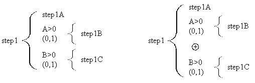
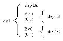
One can include selection at various points in the program. The following represents
a program that has conditions for step2B and step1C.
In this program the two selections are completely independent of each other. In
other words, step1B is executed if the variable A contains a value that is greater
than zero. Step1C is executed if the variable B contains a value that is greater
than zero. The pseudocode for this structure would look like this:
step1A
if(A>0)
{
  step1B
}
if(B>0)
{
  step1C
}
![]() signs between them. In the following
step1B and step1C are exclusive, meaning at most only one of them will be executed.
If both conditions are false then neither one will be executed. Only the first one with
a true condition will execute.
signs between them. In the following
step1B and step1C are exclusive, meaning at most only one of them will be executed.
If both conditions are false then neither one will be executed. Only the first one with
a true condition will execute.
This is equivalent to the following pseudocode:
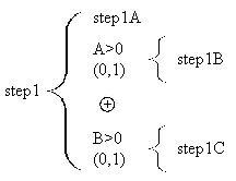
Note the presence of the keyword "else" in the condition line for setp1C. This single
keyword makes the two selections exclusive. Without that word they are not exclusive.
step1A
if(A>0)
{
  step1B
}
else if(B>0)
{
  step1C
}
![]() symbol to
show the exclusivity of the structure, but in this case can appear more than once. Here's
an example of an "if-else if-else" structure with one "else if" and an "else":
symbol to
show the exclusivity of the structure, but in this case can appear more than once. Here's
an example of an "if-else if-else" structure with one "else if" and an "else":
In this case one of the steps step 1A, step 1B or step1C will be executed (but never more than
one), depending on the value
of the variable A. The corresponding pseudocode would look like this:
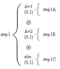
if(A=1)
{
  step1A
}
else if(A=2)
{
  step1B
}
else
{
  step1C
}
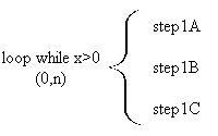
A pre-test loop will contain the string (0,n) indicating that the body of the loop will execute
from zero to n times. Often the condition of continuing the loop is provided with or in place
of the pseudocode name of the step. Here's an example:
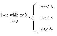
A post-test loop contains (1,n) indicating that the body of the loop will executed from
one to n times. It could look something like this:
Combinations of Sequence, Selection and Repetition